The 1954 South Bend 9” lathe was purchased for $1200 from a home machinist in Noblesville. He delivered the lathe on the cabinet with a trailer on his truck. He also brought a pallet jack to move the whole setup from trailer to garage. We were lucky and it never tipped over. We had to set it on two 2 X 4’s to get it off of the pallet jack. It came with a new 1.5 hp motor (110/220 V) installed, but included the original motor. There were very few attachments: a faceplate and an odd set of collets. The only clearly broken part was a handle on the gearbox. A metal drawer was missing from the cabinet. The main reason I purchased it was that the ways were in very good shape. The cross slide holding the cutting tool moves along the ways and any problem with them impacts the accuracy of the cut. There seemed to be very little wear and the original scraping was still visible in some places. It was clearly dirty and the paint was peeling (three layers as I discovered later.) I purchased a book detailing SB 9 and 10 restoration. The book also came with a set of the necessary felt plugs that help to distribute the lubricating oil. The plan was complete disassembly, thorough cleaning, part repair or replacement, and reassembly.
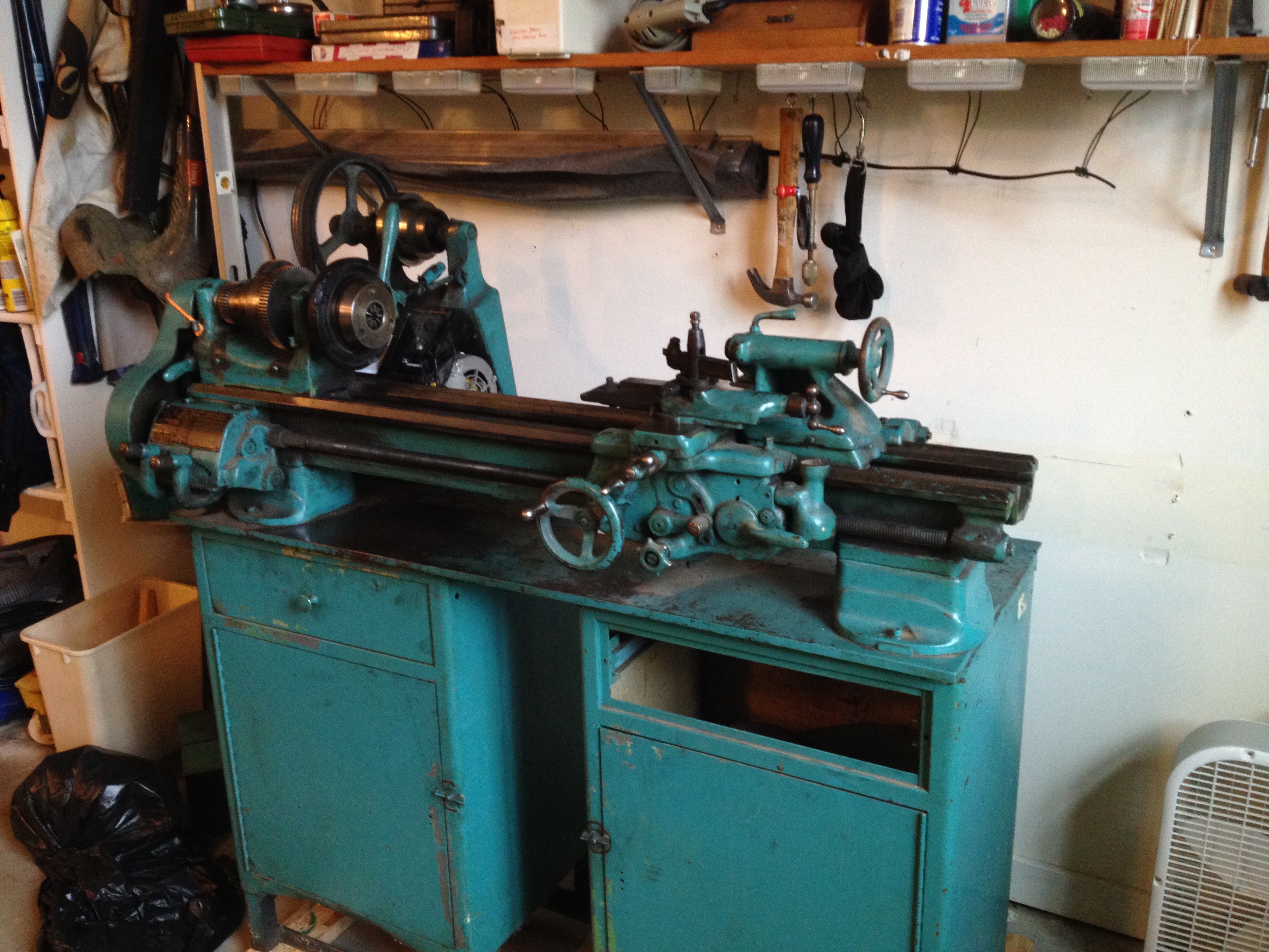
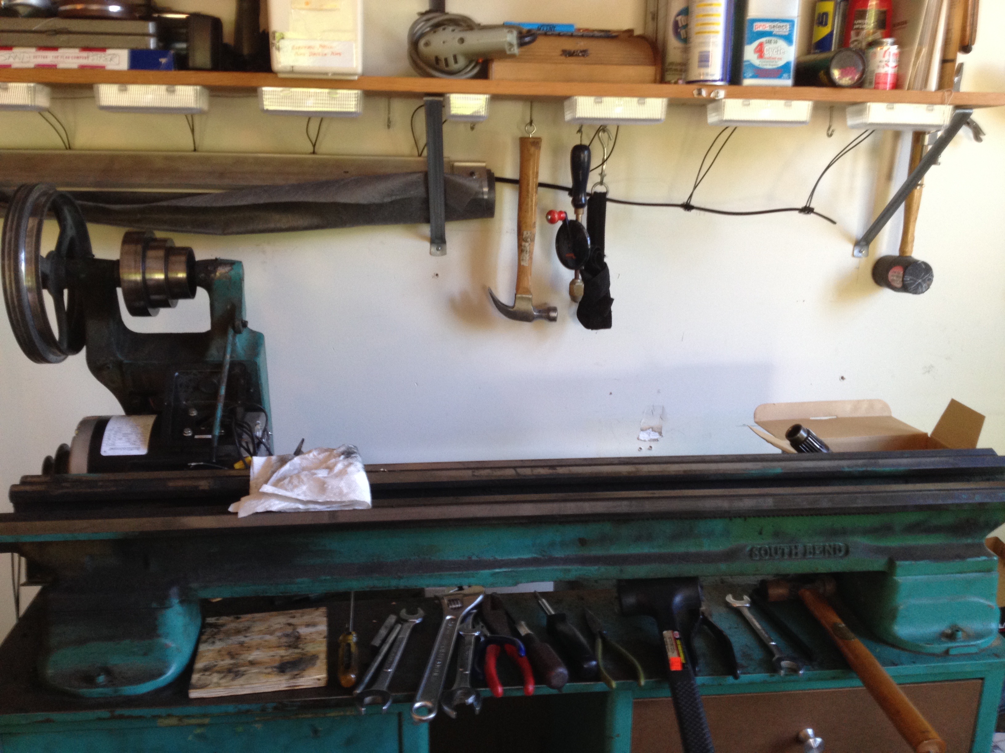
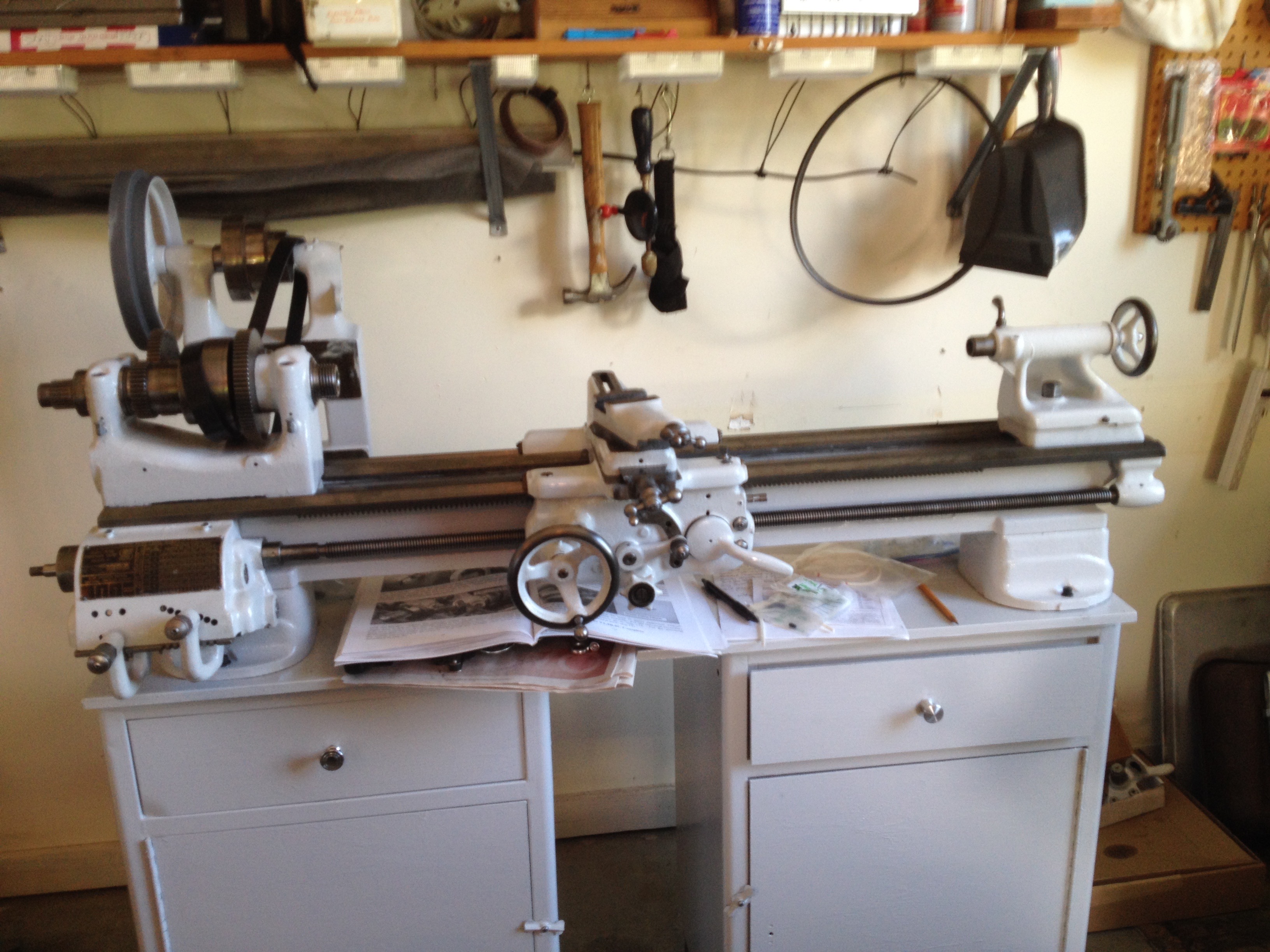
The photo below shows the lathe as delivered. The collet holder (black rubber ring) is attached to the lathe spindle on the left. Zooming in will show hints of the dirt embedded everywhere.
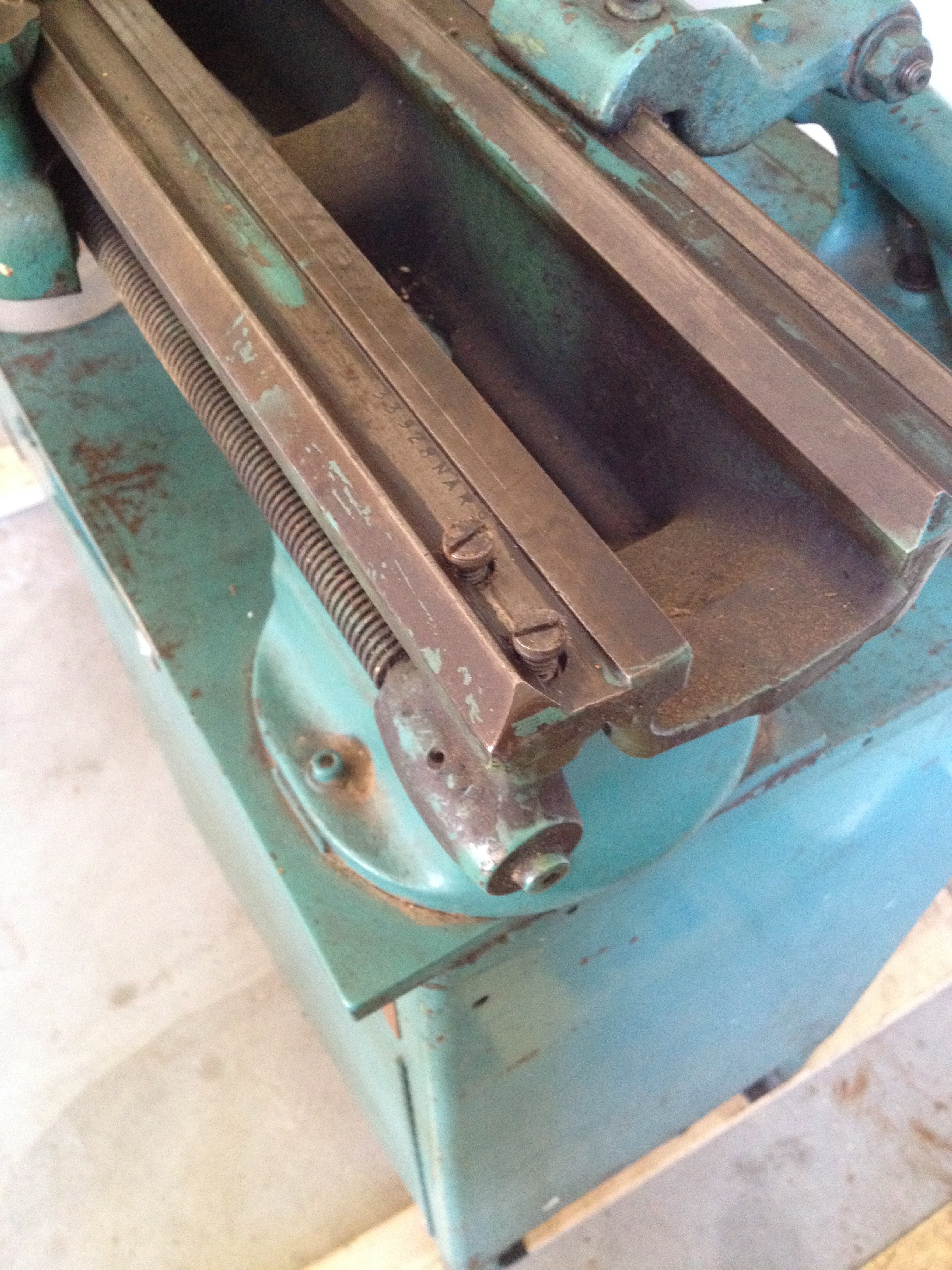
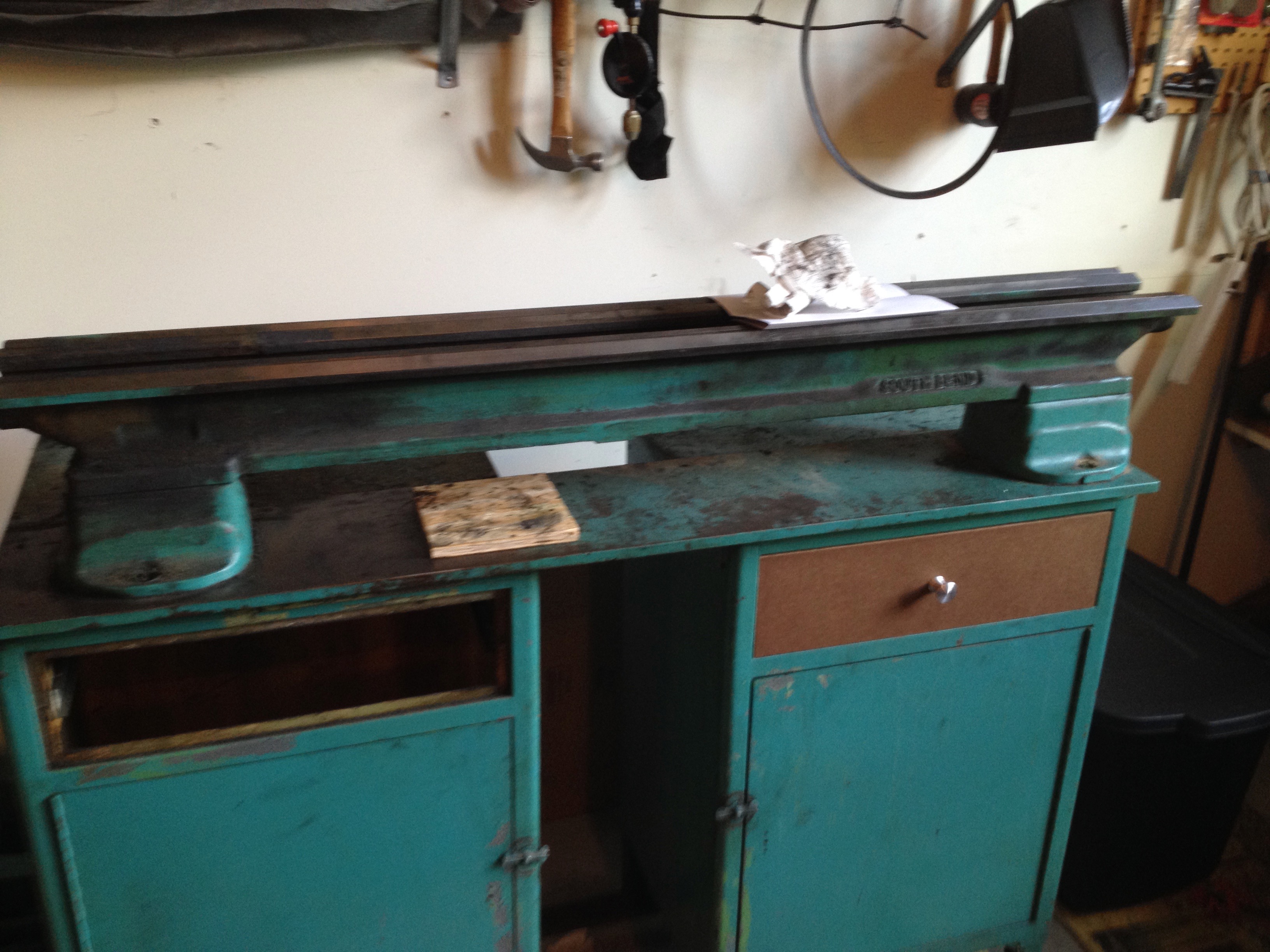
Disassembly began with removal of the tailstock resting on the right end of the lathe bed or ways. The tailstock has a round handle on the right end. In the picture below you can make out the serial number that allowed me to determine the year the lathe was manufactured. Just above and to the left of the serial number you can make out some swirly marks on the flat part of the ways. These are scraping marks made by the factory worker who “scraped the ways” by hand to make them extremely flat (less than 0.001” of deviation).
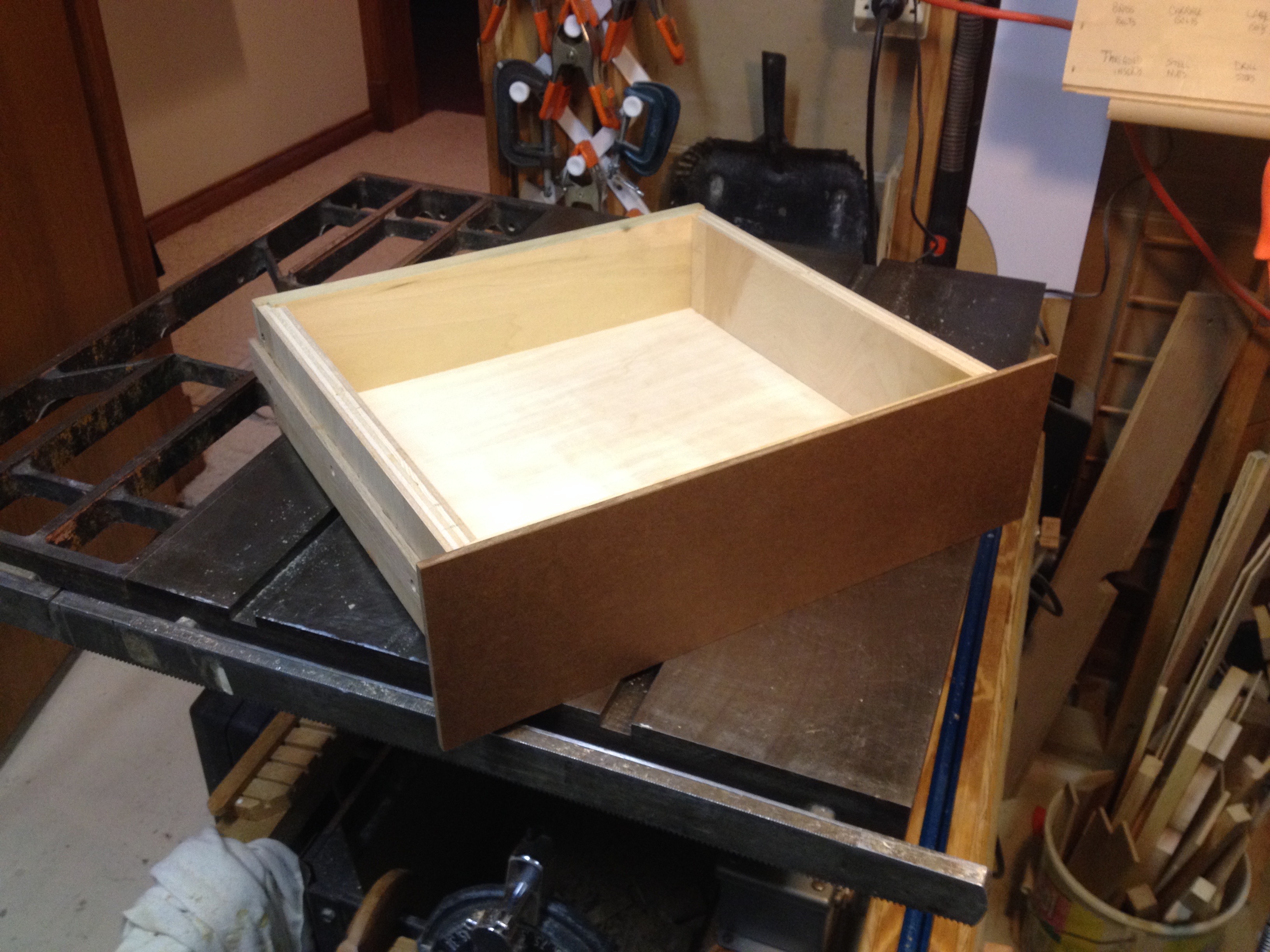
The carriage was removed next. In the top photo it is the part with the round handle on the front. A new drawer was made at this time as shown below.
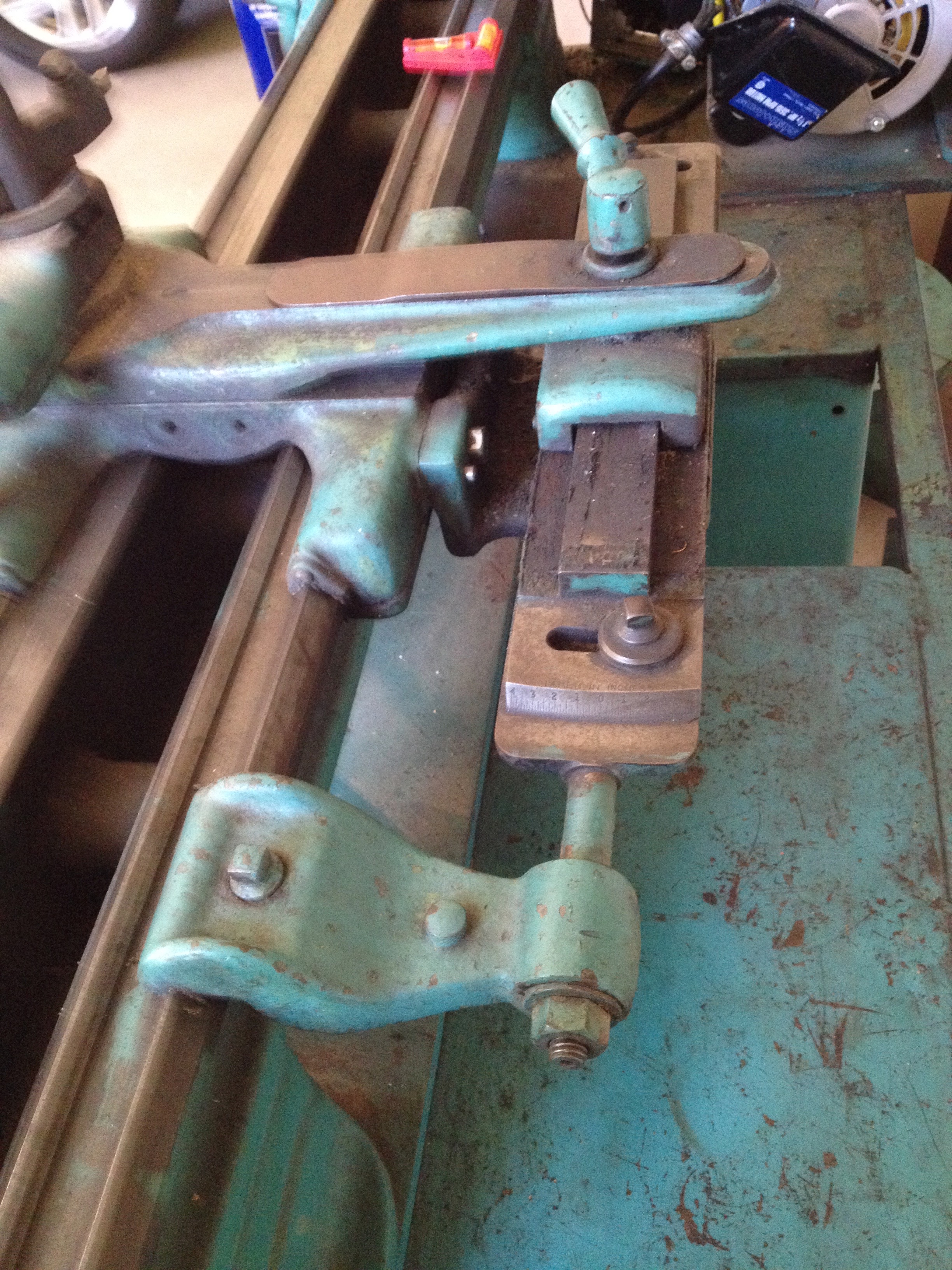
The carriage has a taper attachment seen in the photo below. This accessory was included in the purchase. It was removed at the same time as the carriage. Zooming in on the rail the taper attachment slides on you can start to get a feel for the crud that infested every nook and cranny of the lathe. It is a previously unknown, hard and brittle substance composed of 50 year-old grease and metal chips.
Headstock removal was next. The gear covers have been removed from the headstock in the following photo. The collet chuck and the box holding the collets are in the drawer below the headstock Notice how clean these gears and pulleys are. They were replaced by the previous owner. I do not know why he only replaced the pulley/gear set and did not clean up anything else on the headstock.

Below are the change gears attached to the left side of the headstock. They would have been removed to replace the gear set mentioned above. They were put back in place dirty! In any event they were removed before headstock disassembly. These gears link the rotation of the spindle (holding the workpiece) to the left-right movement of the carriage or cross-slide.
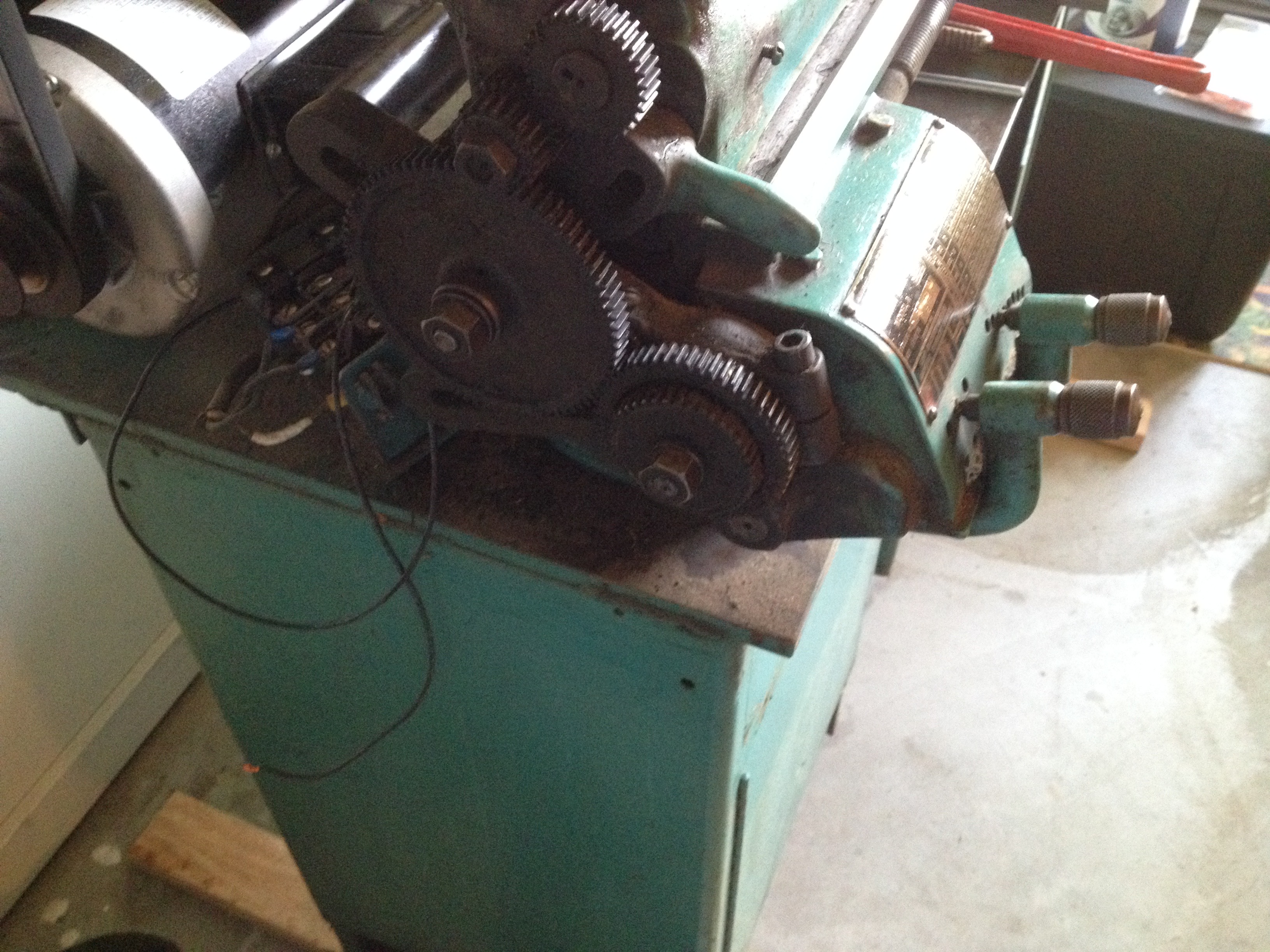
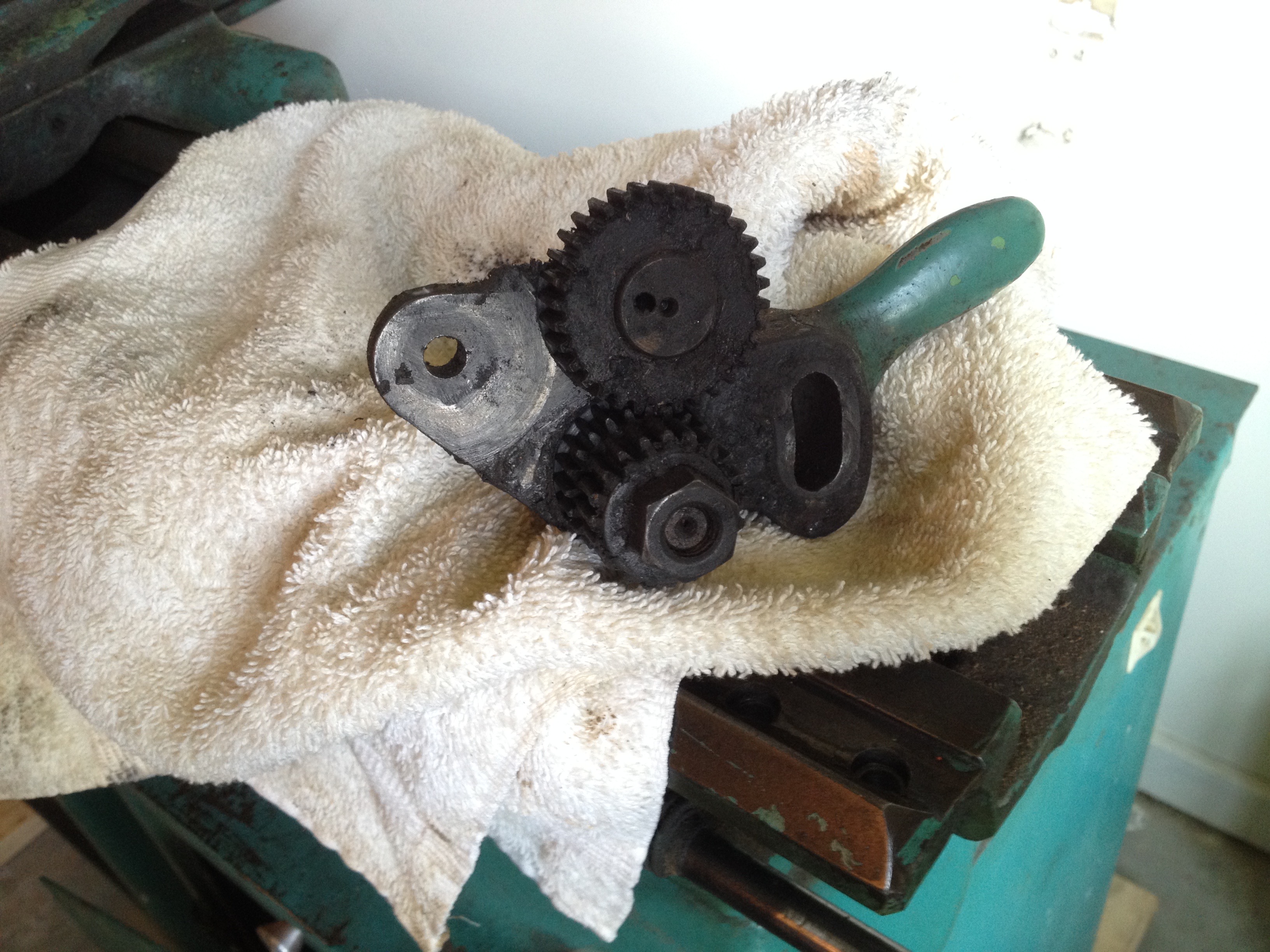
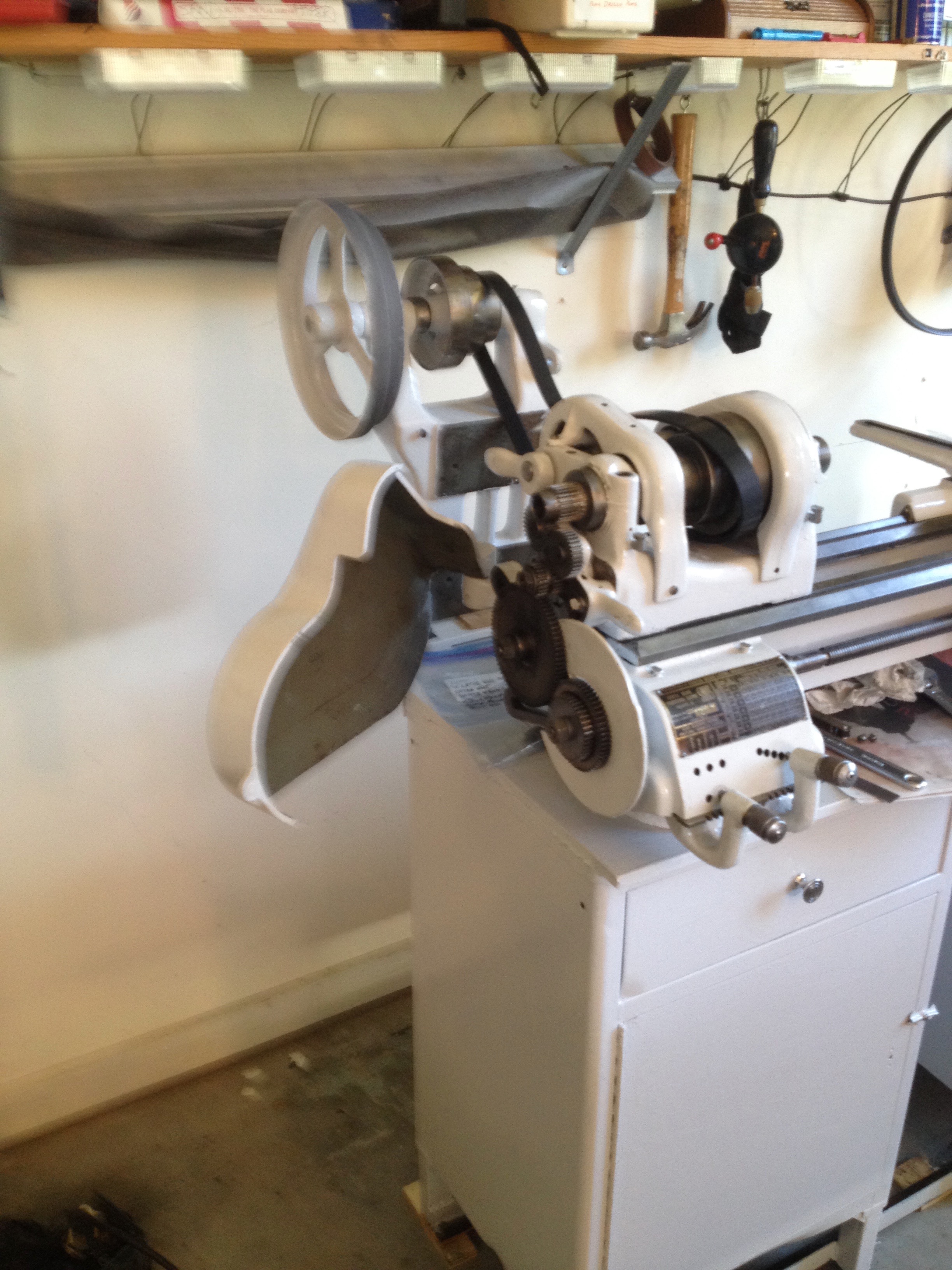
Disassembling these change gears was next. The handle in the upper center of the picture links, unlinks or reverses the spindle carriage connection. It is shown in all of its crud encrusted glory below.
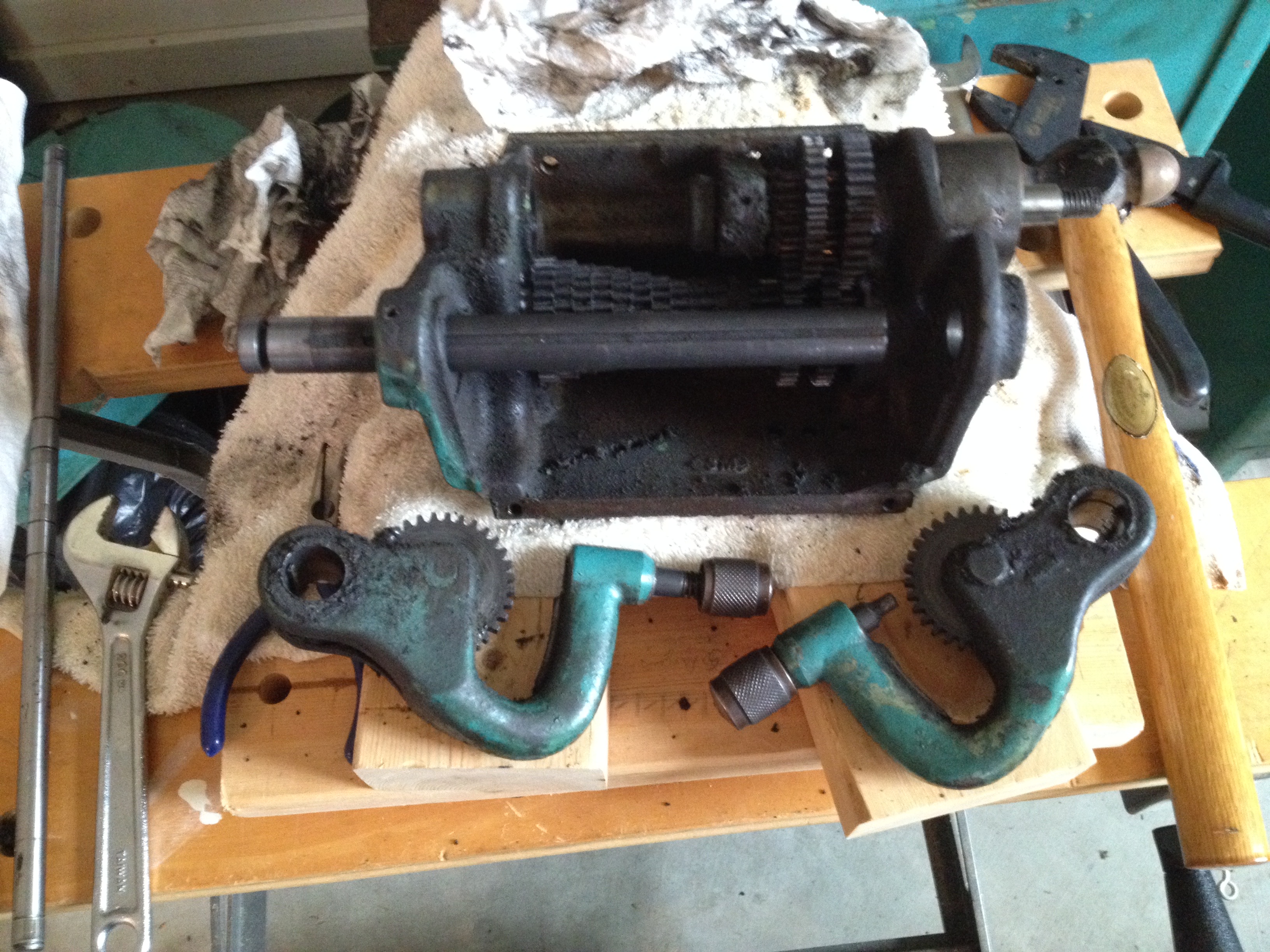
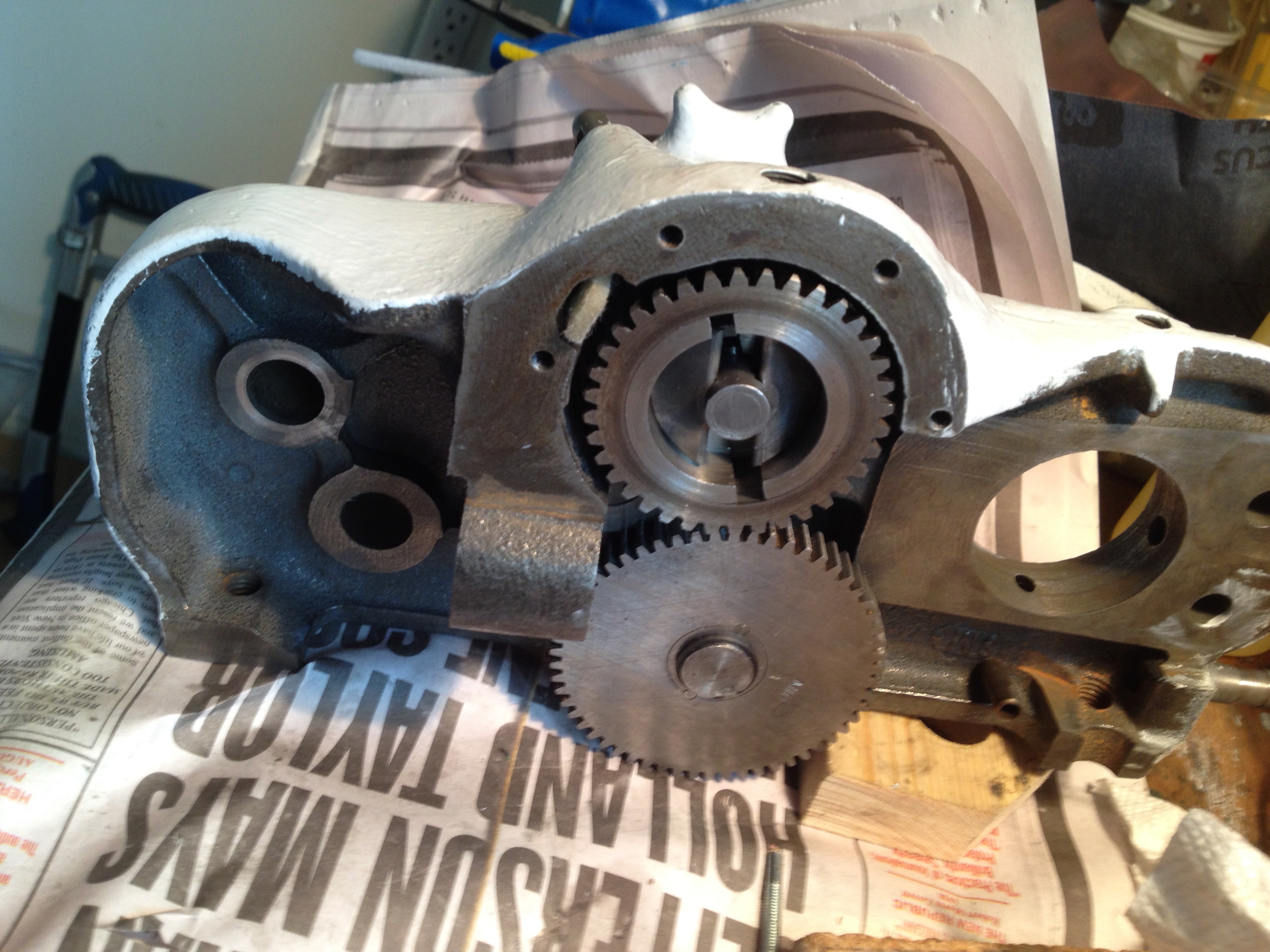
Removing the gear box was tackled next. It sits just below the headstock on the front of the lathe. You can see it to the right of the change gears with the brass plate and the two levers. (Two pictures above) One of the levers was broken. It looked as if something very heavy was dropped on it, though the break cannot be seen in the photo. As you can see the gearbox is full of cruft. It amazes me that the gears were still in good shape and now work fine. Maybe after the handle was damaged the gear box was never used again. The gear box was completely disassembled and the gears kept together in groups by linking them with wire. Disassembly means removing the various tapered pins and "keys" holding the metal parts together. The pins were removed with pin punches. Both the pins and the keys were usually frozen in place and required significant effort to remove without damaging the parts.
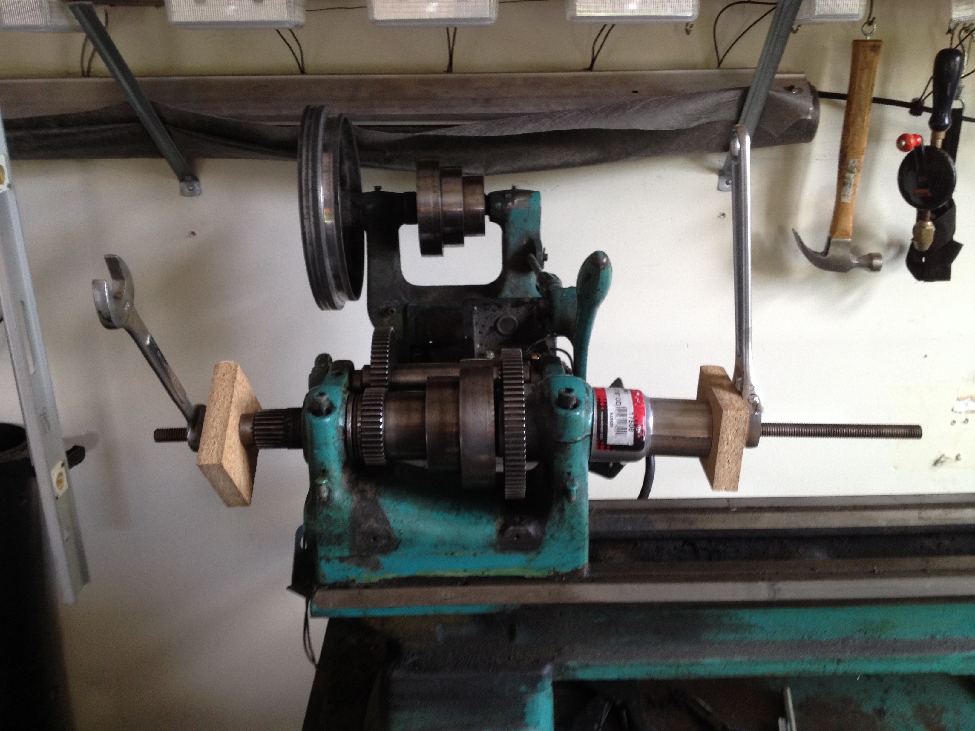
The spindle needed to be removed next. The spindle is a tube that runs through the headstock. It sits in needle bearings in the headstock. This is one of the most important parts of the lathe. Recommendations on the web indicated the best way to force it out of the bearings was to use a threaded rod. I used a wood block on each end as well as a piece of pipe on the right end. The pipe was big enough to fit over the nose of the spindle and rest against the headstock proper. The spindle should be forced out to the right as the nuts are tightened. You can see in this picture what really happened. The threaded rod started to bend. I could not budge the spindle this way. I next tried a wooden block on the left end of the spindle and a large hammer. Still no luck so I called the original owner as he had removed the spindle previously to replace the gear/pulley set. He came over and being about twice my size was able to knock it loose with a hammer. A really nice guy!
The motor and its mounting support were next. These were relatively straightforward compared to the previous parts, just heavy and bulky.
The bed and feet were the last parts removed. They were easy to separate, one bolt in each case. I was able to move the bed by hand to the back of the bench. The feet were secured to the 1/2" thick steel bench top by four bolts each. The bed was lowered to the floor for clean up and painting via a set of pulleys suspended from hooks (previously used to hold bikes) in the ceiling. These are shown later in a reassembly photo.
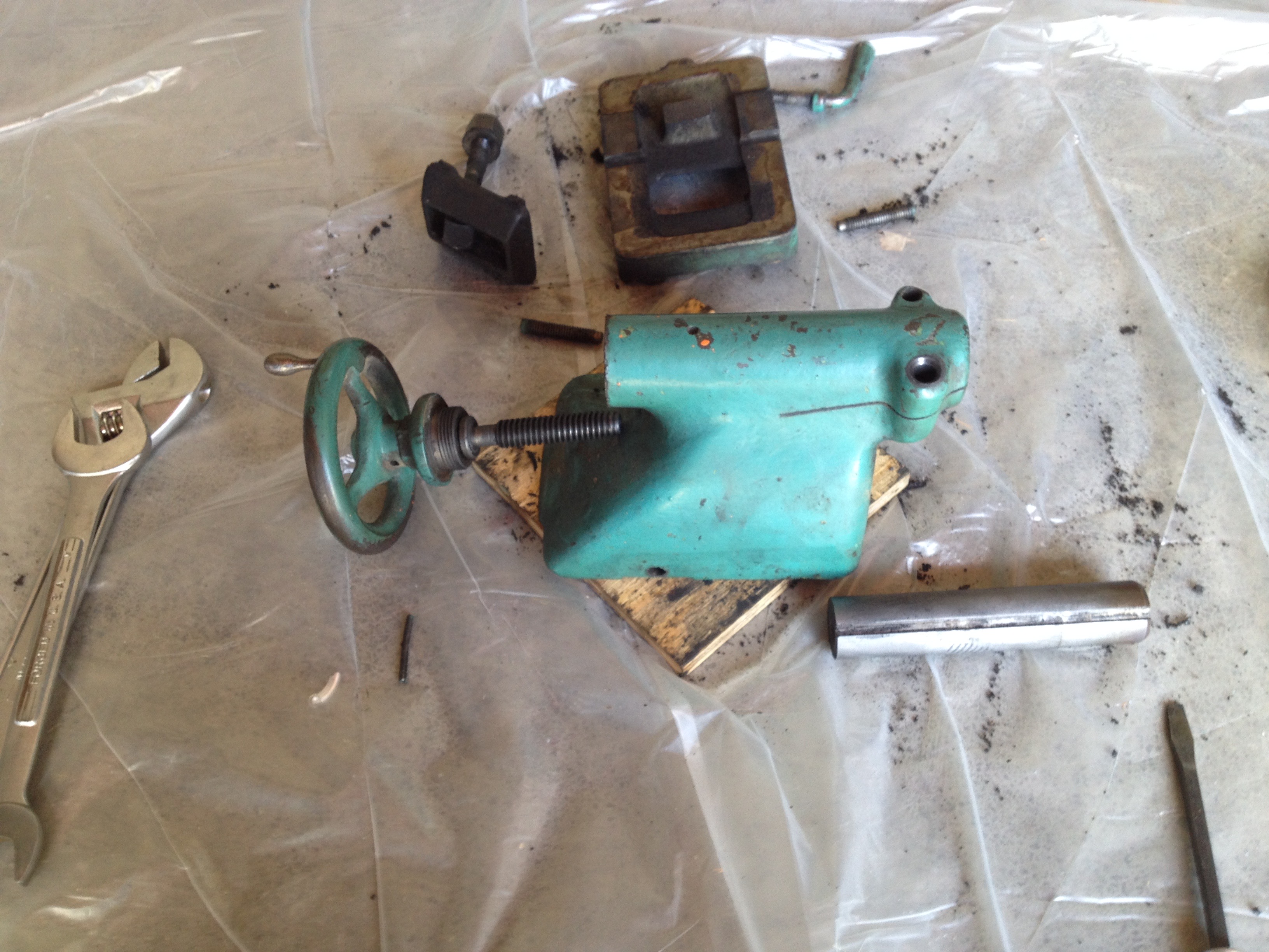
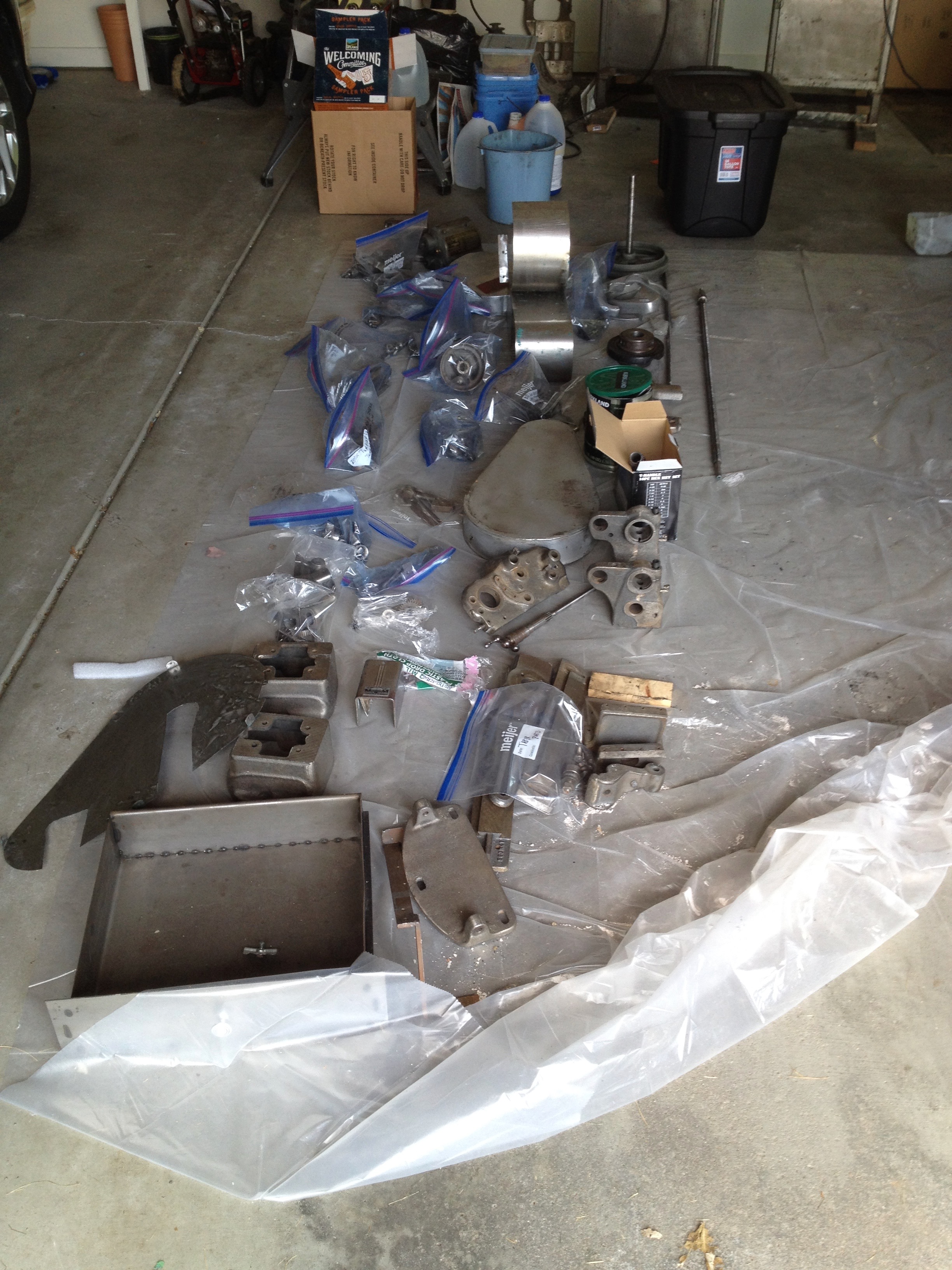
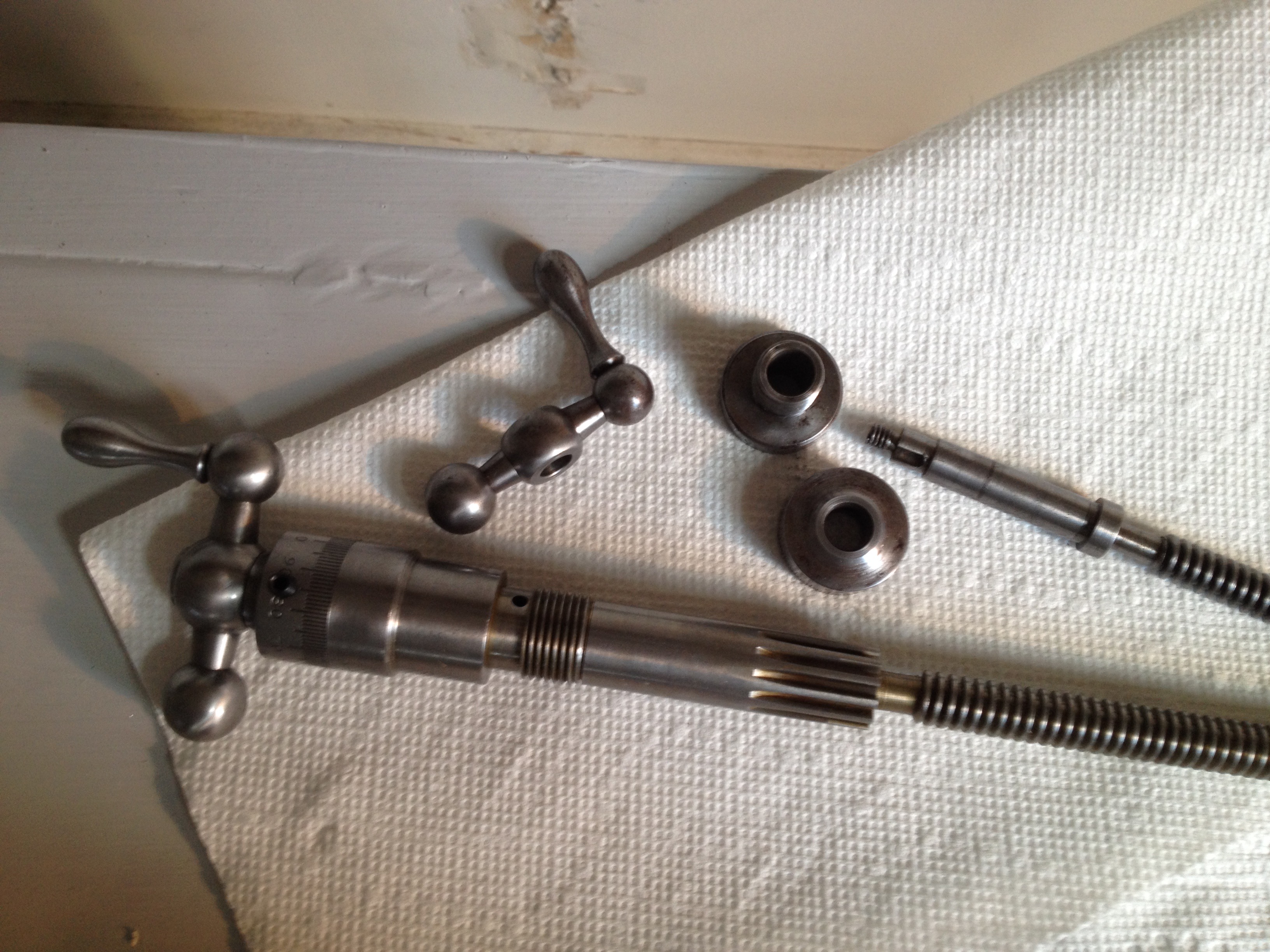
Pictured above is complete disassembly of the tailstock as an example. The round handle was also removed from the shaft and bearing. Paint stripping and cruft removal were next. I used a a degreaser known as "purple" (ZEP Industrial Purple Degreaser) as it is purple and a separate orange paint stripper (Citri-Strip). I purchased a large plastic tub and diluted the purple with distilled water and placed the parts in it to soak overnight. Only a few parts were cleaned at a time. This is due to flash rust. It was summertime when I got to the cleaning so I had to consider humidity. After paint removal the parts were soaked and various brushes from steel to tooth brush were used to reveal bare metal. The purple solution was rinsed off with water and the parts were then rinsed with acetone. This gets rid of the water, but it evaporates so quickly that it cools the part and if you are not careful water condenses on it causing almost immediate rusting. I then put a light coat of oil on the part for storage prior to assembly. My fingernails were black throughout most of the cleaning months.
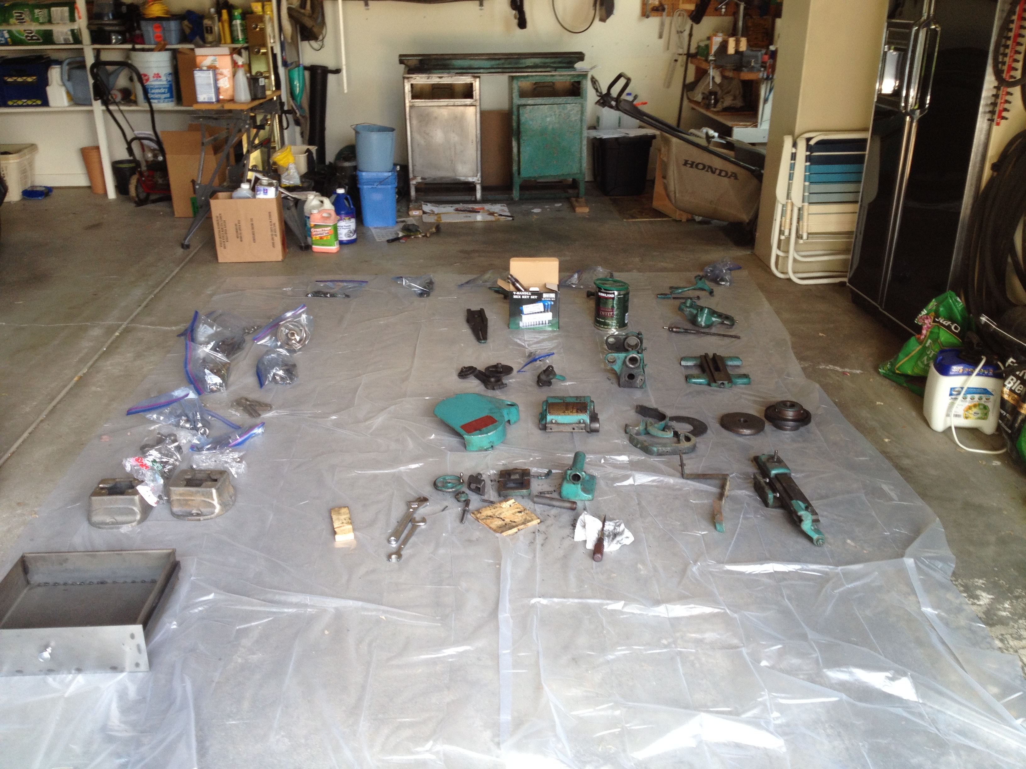
Above is a shot of the cleaning process in progress. The cleaned parts are bagged on the left. There is also some progress cleaning the bench. It is easy to notice the difference between the bagged parts and the dirty parts on the right.
The parts have all been cleaned and the bench is as well. Now it is time for painting and assembly. I went to a paint dealer for the paint. This was a mistake, I should have just followed instructions from the internet. I purchased a primer and a finish coat. They only had the offwhite color for the finish coat. I would have preferred something darker to hide the eventual dirt. The real problem was the primer. It was so thick and dried so fast that it would dry in one section before the adjacent section was painted so joining the two left a very bumpy finish. I probably should have thinned it in retrospect. Except for the cabinet only the unfinished cast surfaces were painted. So some parts had significant painting (gear covers), while others had minimal or no painting (e.g., gears).

The picture above shows the pulley system used to raise the bed up and onto the feet. The bench and bed/feet have been primed and have the finish coat of paint. It is difficult to see, but the bench has been leveled with wooden pads under the legs. It is very important for a lathe to be properly leveled. Otherwise the bed will twist slightly (a few thousandths of an inch) and the lathe will then always cut a slight taper. Once the bed was attached to the feet they were shimmed to make sure the bed was as level as possible. I used an app on the phone as a level (accurate to the nearest 0.1°).
Here is the carriage in the midst of assembly. You can see some flash rust in the lower right. The bumpiness of the painted surface was not due to the primer here. The majority of the parts including the carriage housing were made from cast iron. The iron was cast in a sand mold. Only surfaces that mated with other metal surfaces were machined, so the outside painted surface is slightly bumpy. At about 10 o'clock on the top gear you can see one of the white felt pads that were put in various holes in the castings. They help to transfer oil from the oiling points There are about 15 places to add oil across the entire lathe in addition to lubricating the ways.
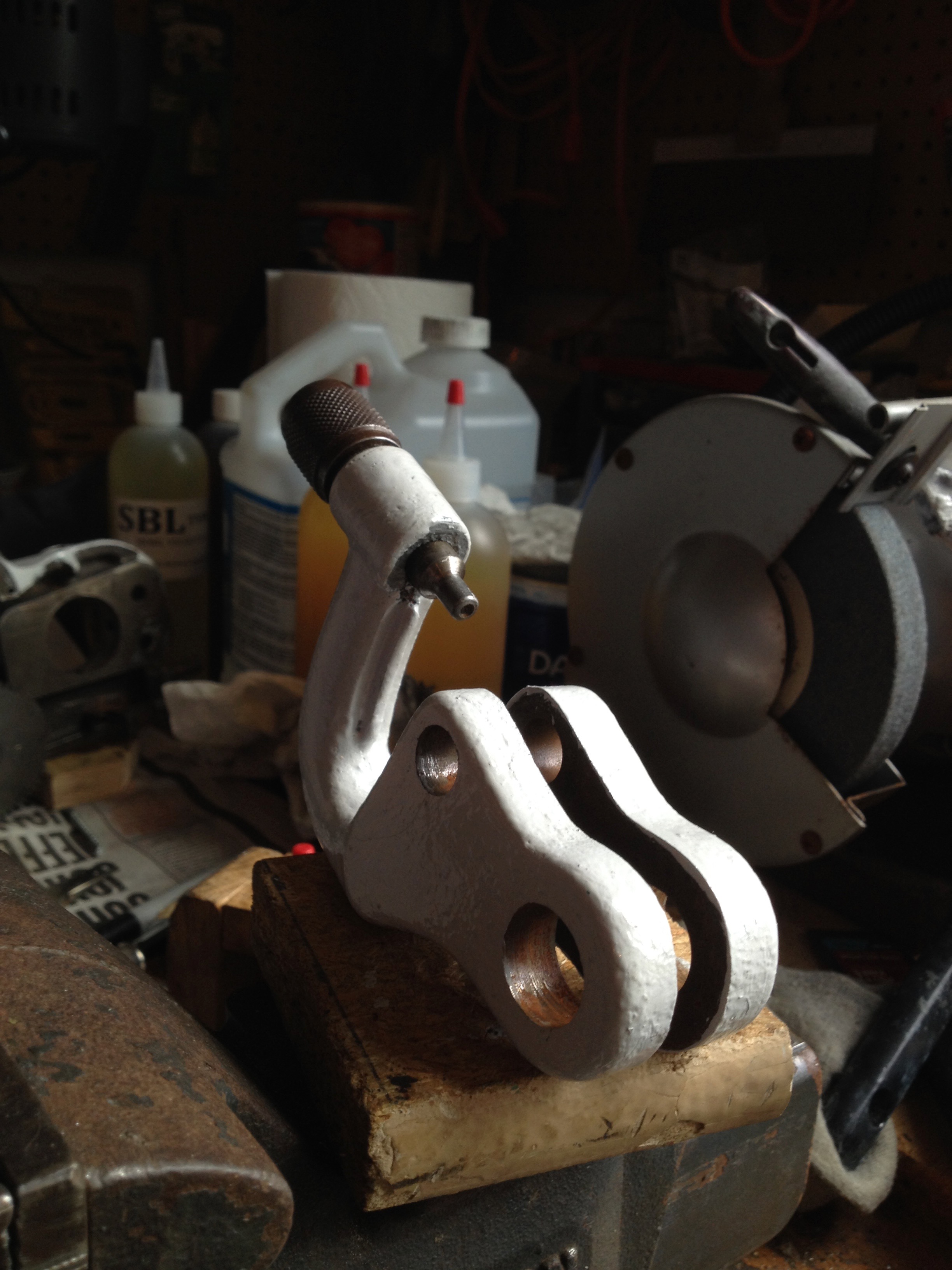
A new handle had to be purchased for the gearbox. There was also another gear that had to be purchased. Luckily, there is a pretty active community of South Bend lathe owners and parts can be found. The handle was cleaned up and painted as shown.
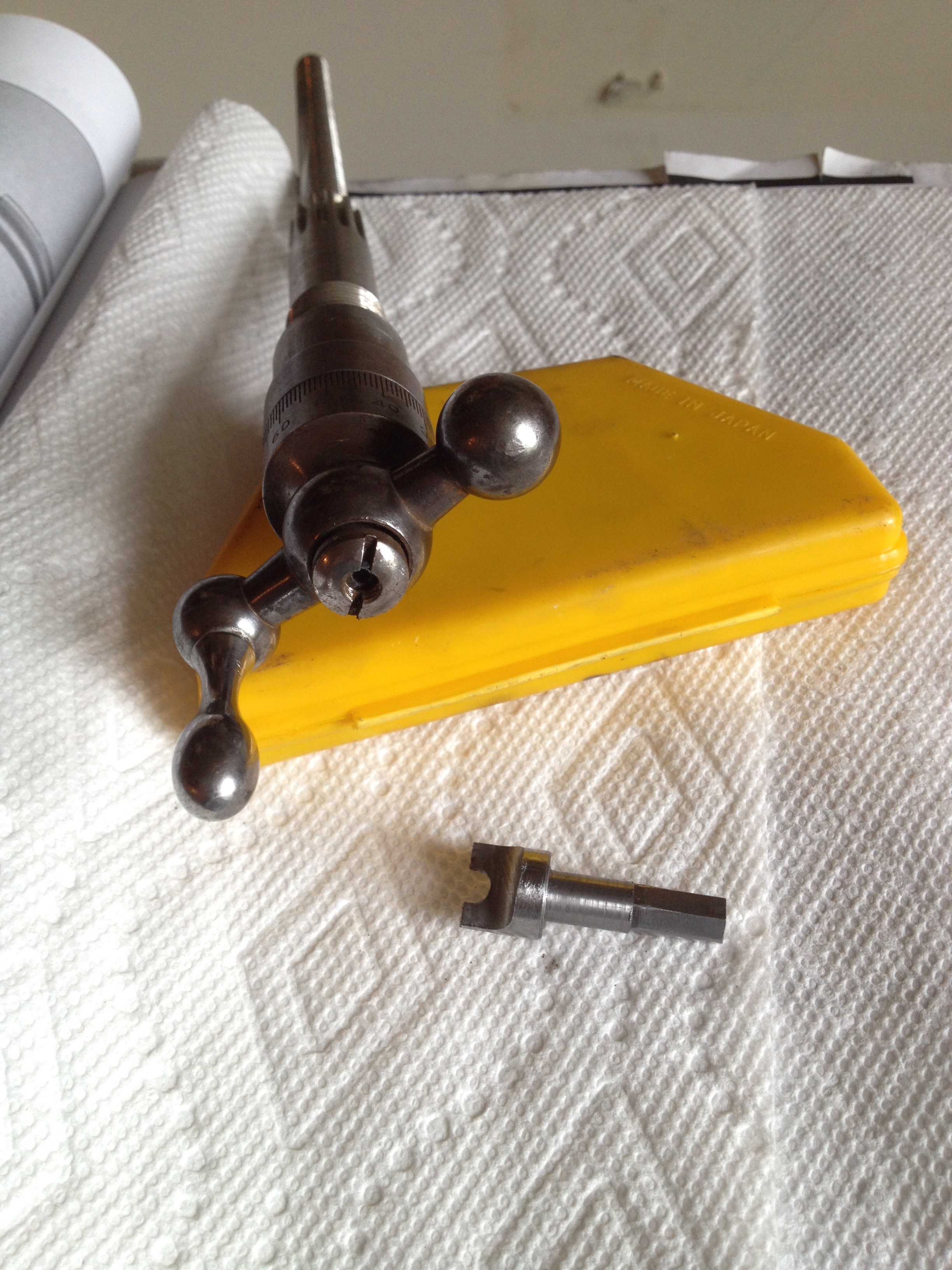
The cross slide screw (moves the cutting tool toward and away from the workpiece) needed to be taken apart for cleaning. As you can see the screwdriver slot is bifurcated. You can buy the special tool needed to remove it, but I decided to make one instead. I made it from a low carbon steel rod and put a hexagon cross section on the end to hold it in a handle for inserts. The low carbon steel allowed me to harden the tool by heating it to "cherry red" with a propane torch and quenching it in motor oil. It worked like a champ and saved me $45.
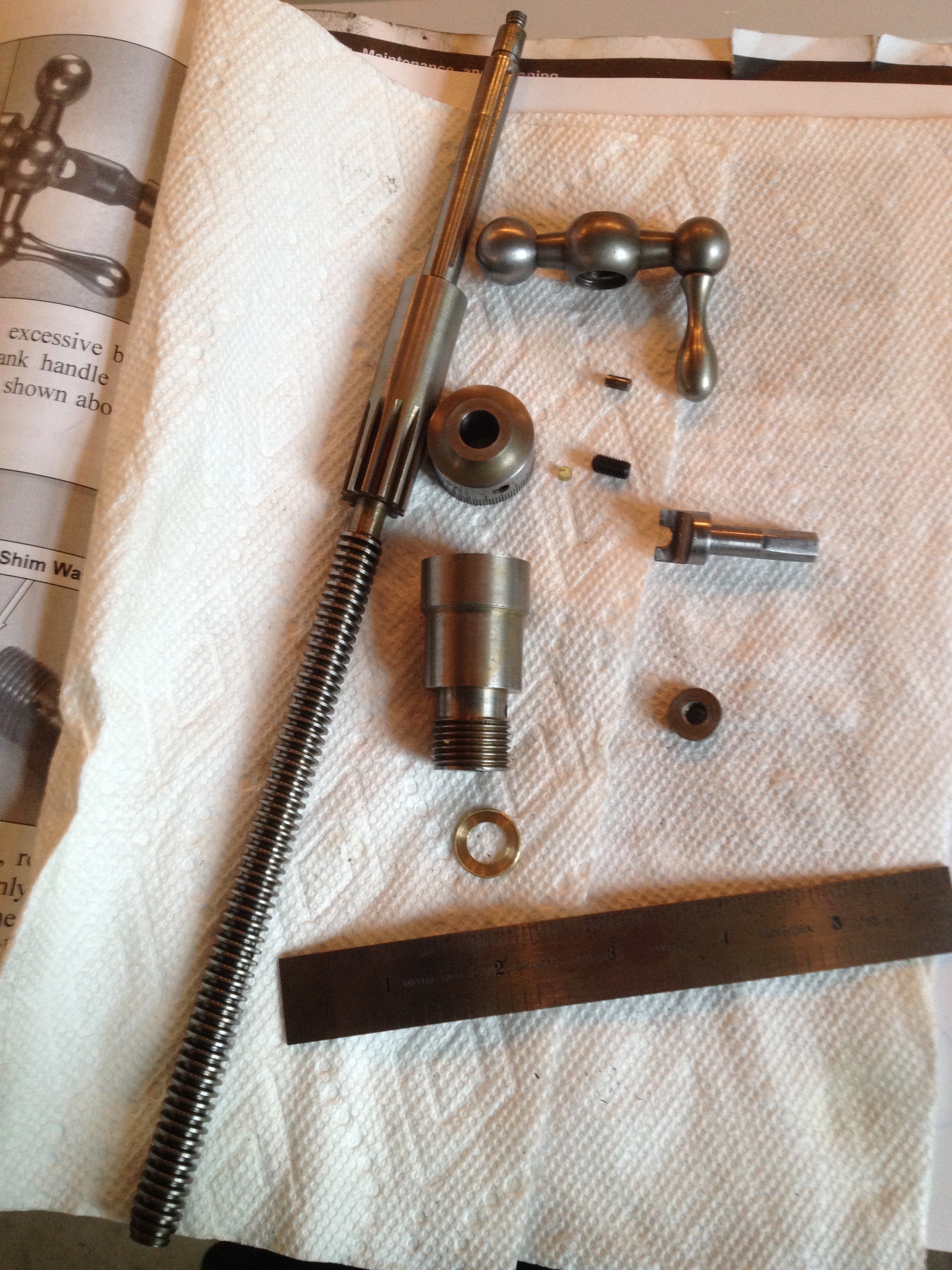
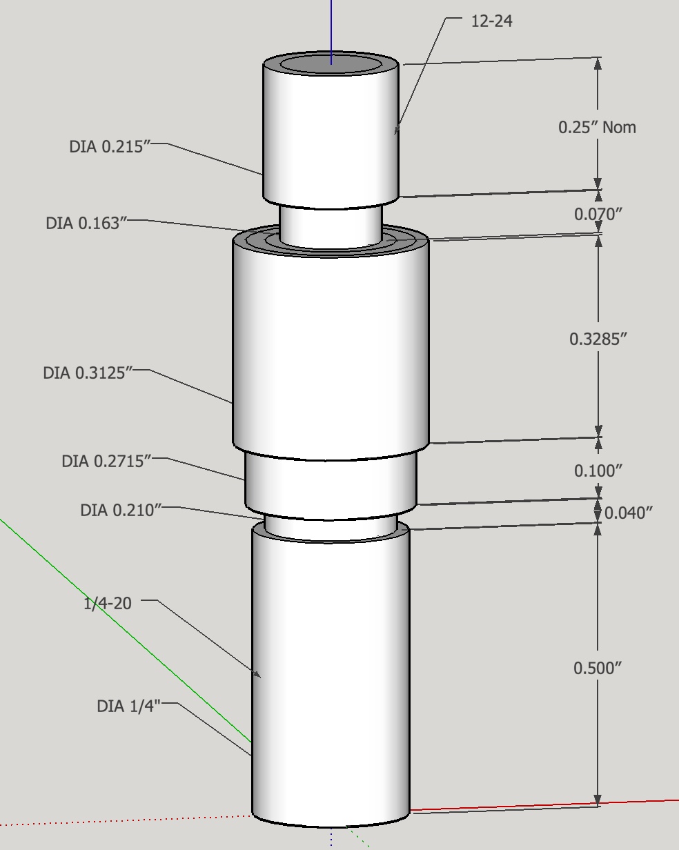
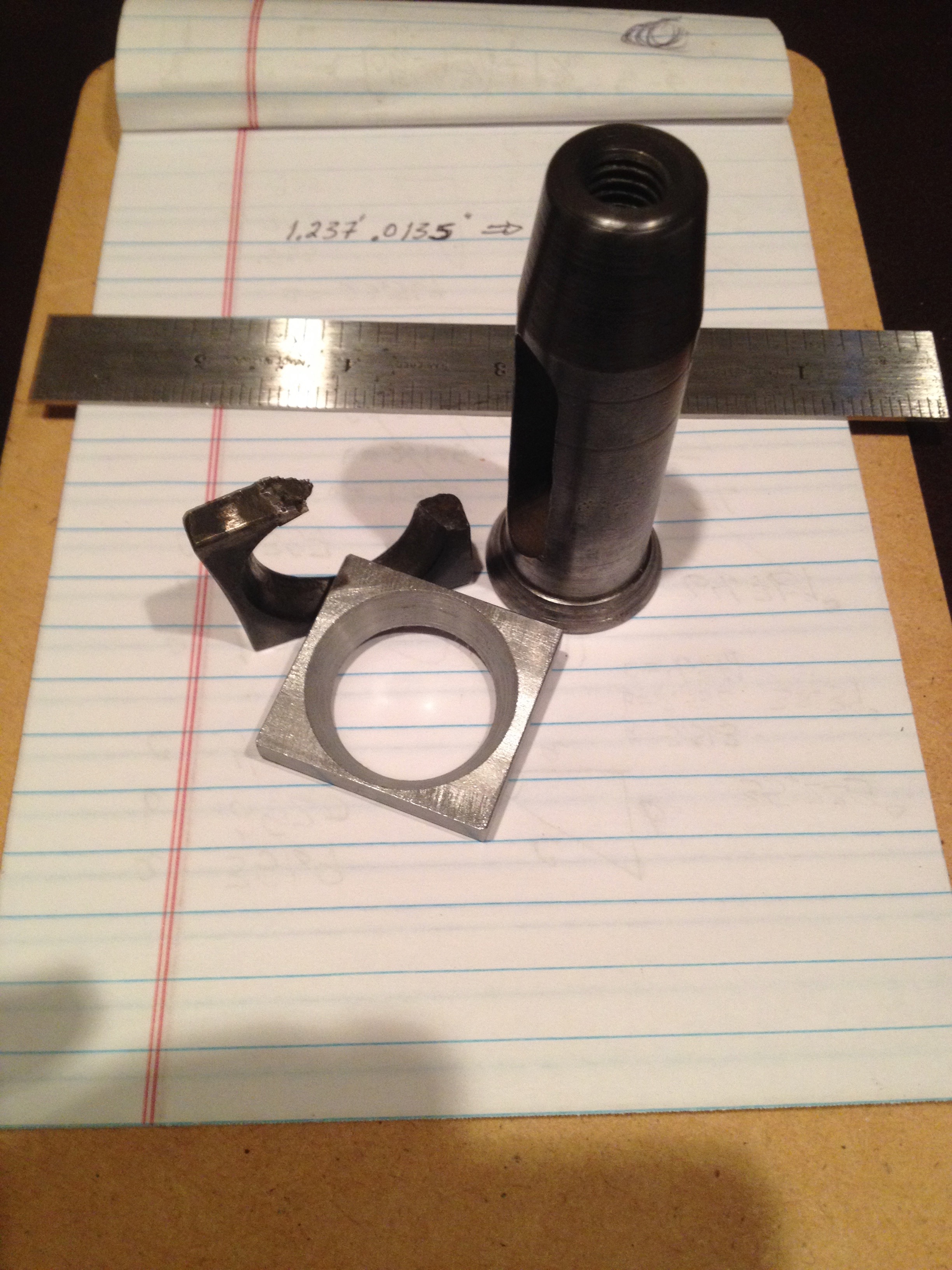
The most complex repair was on the smaller of the two cross slide screws seen below. The threads on the end were damaged beyond repair (hard to see this in the picture). It was repaired by removing the end of the shaft and making a replacement. The old screw end was drilled and tapped for 1/4-20 threads to match the new part. A SketchUp plan for this part is also shown below.
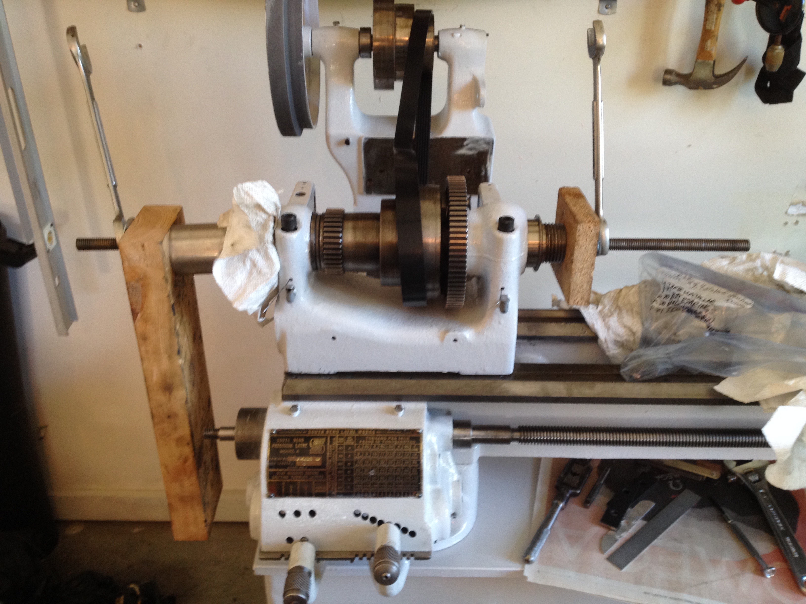
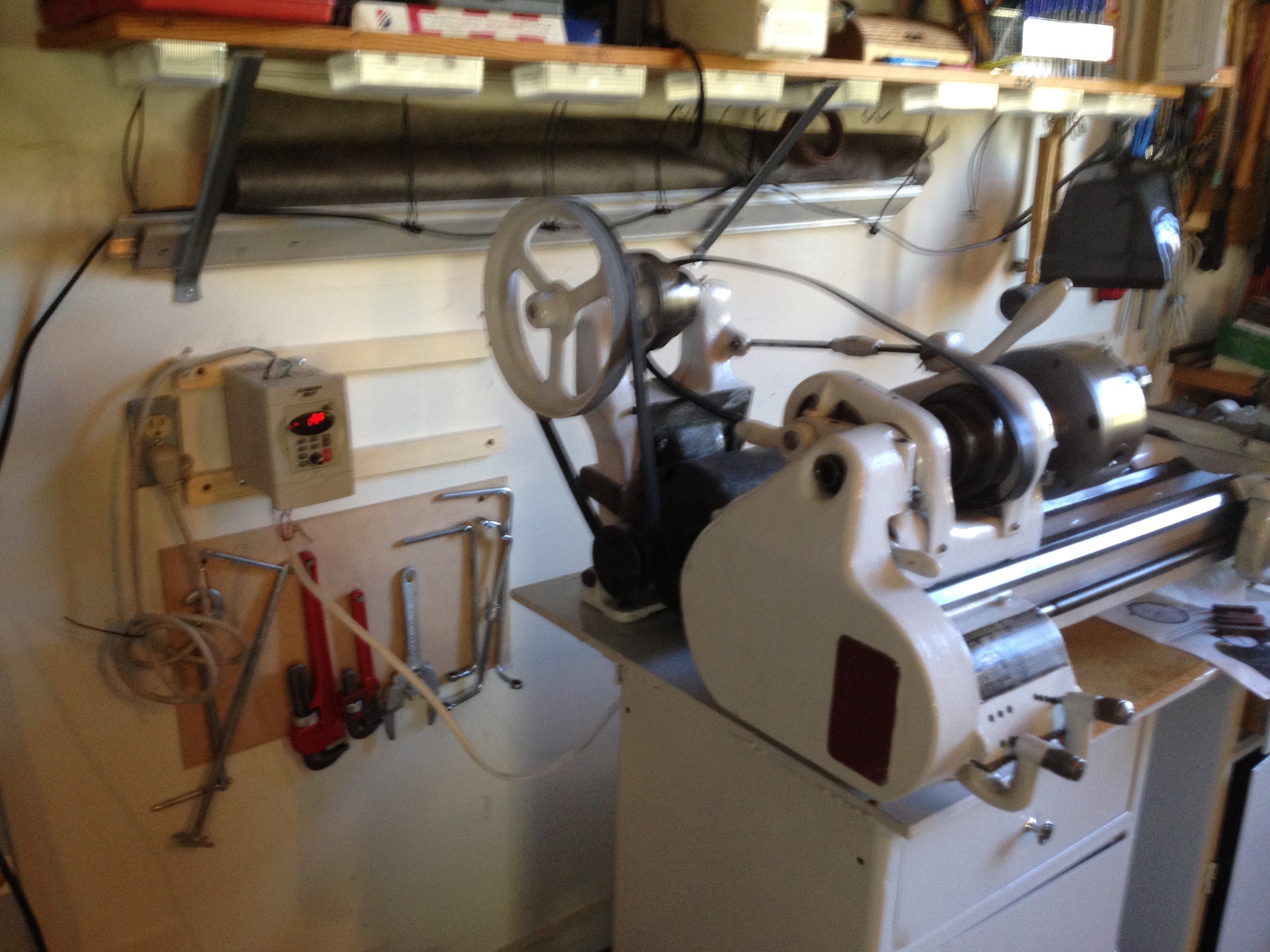
The image below shows the "screw" method of putting the spindle back into the headstock. It worked this time!!! The purchased serpentine belt (these are difficult to find by length) is already installed along with the motor mount in back. The lead screw (long screw that stretches across the face of the lathe and drives the carriage, if desired) is also installed along with the assembled gearbox.
Below is a shot of the lathe after assembling and installing the carriage, cross slide and the tailstock. The book used for this rebuild is below the carriage. If you look carefully you can see the felt strips in a plastic bag to the right of the book. These were snaked through holes in the walls of the headstock, gearbox and carriage. In this picture you can also see the aluminum knob on the new drawer on the right. This was made on the small lathe in the basement and is similar to the original steel knob on the left.
The slightly out-of-focus picture below shows the change gears and gear covers installed on the headstock.
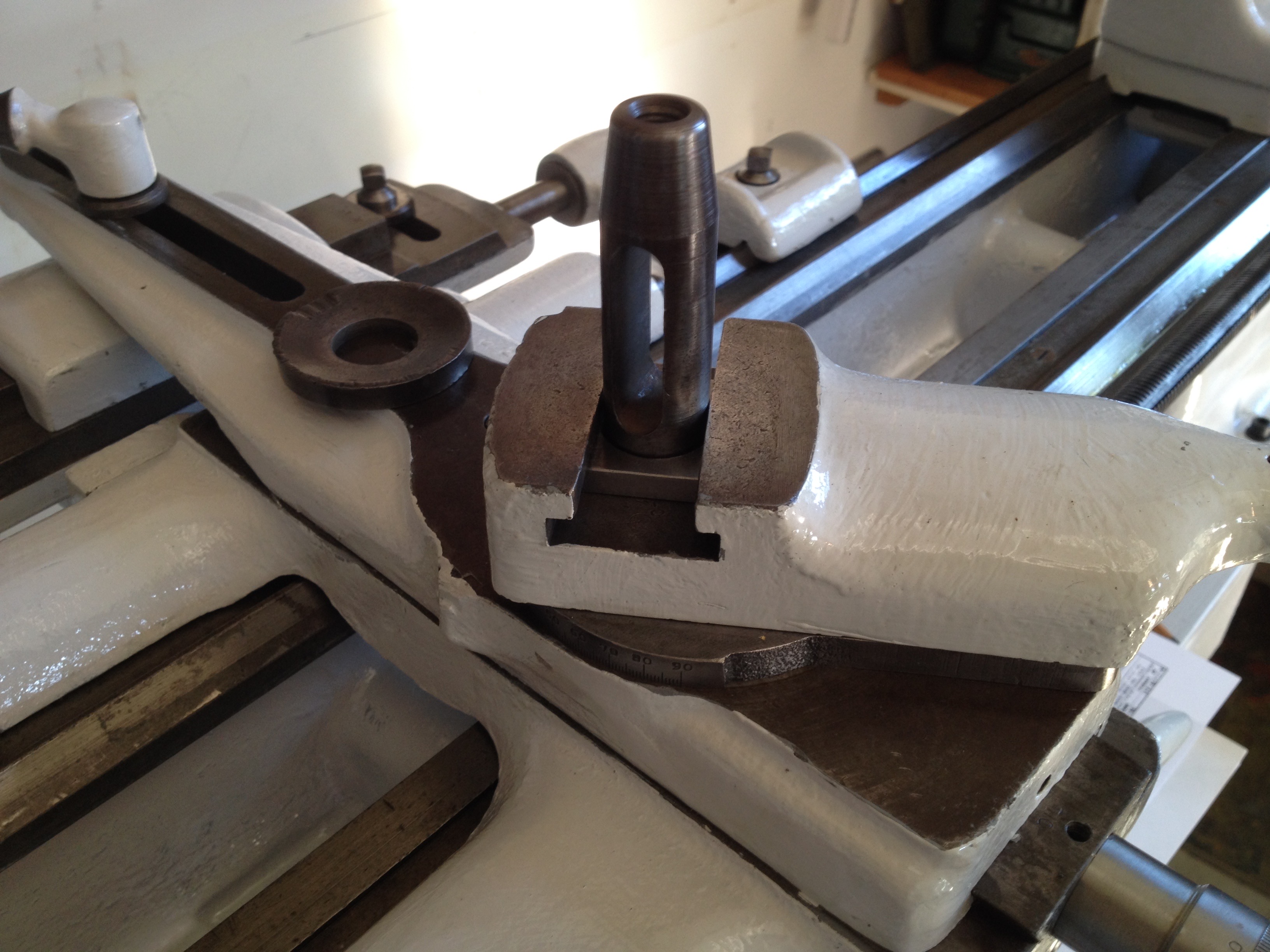
The next challenge was a fairly simple repair job. The picture below shows the toolpost and the broken washer that holds it in a tee slot in the cross slide (easily seen in the second picture). A replacement was made from steel plate. The toolpost works by screwing a bolt through the top of the post down to a tool fitting through the slot in the post. The tool pushes down on the cross slide and pulls the washer up against the top of the tee slot. Cranking down really hard on the bolt must have broken the original washer and subsequent tightening only served to twist the washer out of shape. The extra washer in the second picture sits on top of the cross slide, under the tool, and serves to raise the tool tip to the center height of the spindle.
Here you can see the motor and the inverter have been installed. I decided to use the original motor as the newer motor used too many amps for the 15 amp breaker in the garage. The new motor could be wired for 110 volts, whereas the old required 220 volts and three phase current. Consequently, I had to purchase the inverter. It will not work on a GFCI circuit so I had to run a new outlet from the ceiling lights.
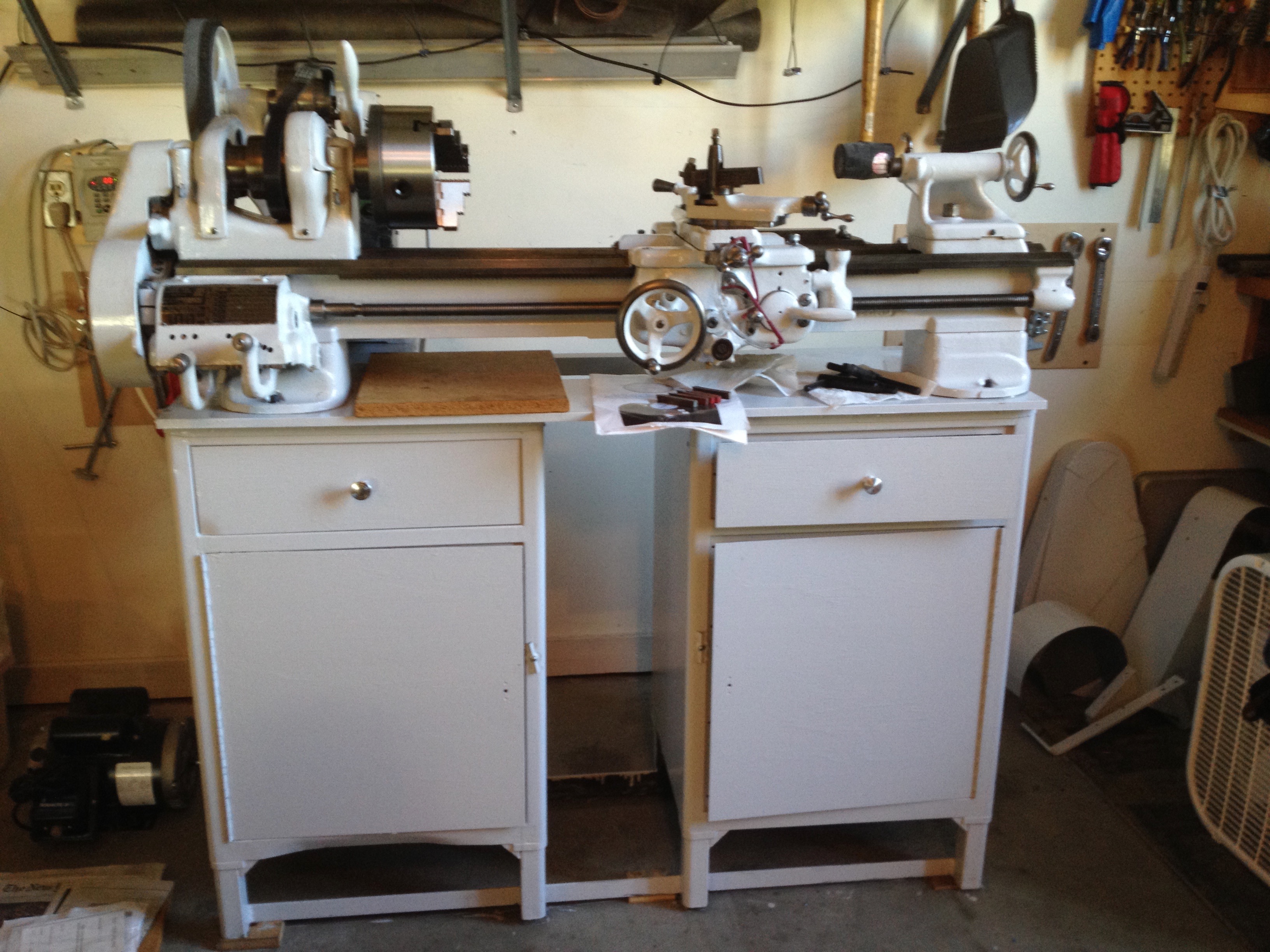
The last shot of the lathe below also shows one of the new chucks purchased. It is a 3-jaw chuck and was purchased along with a 4-jaw chuck. The three jaws of the former all move in concert, while the jaws on the 4-jaw chuck are independent. So the 4-jaw chuck is used for square, rectangular or odd shaped parts. It is also used when you need to get the part concentric with the spindle to 0.001" or less. The 3-jaw chuck will only give concentricity with the spindle to 0.002-3". They cost about $150 each and weigh 40 lbs. The board underneath the ways is placed on top of the ways to protect them when the chucks are put on or taken off the threaded spindle.
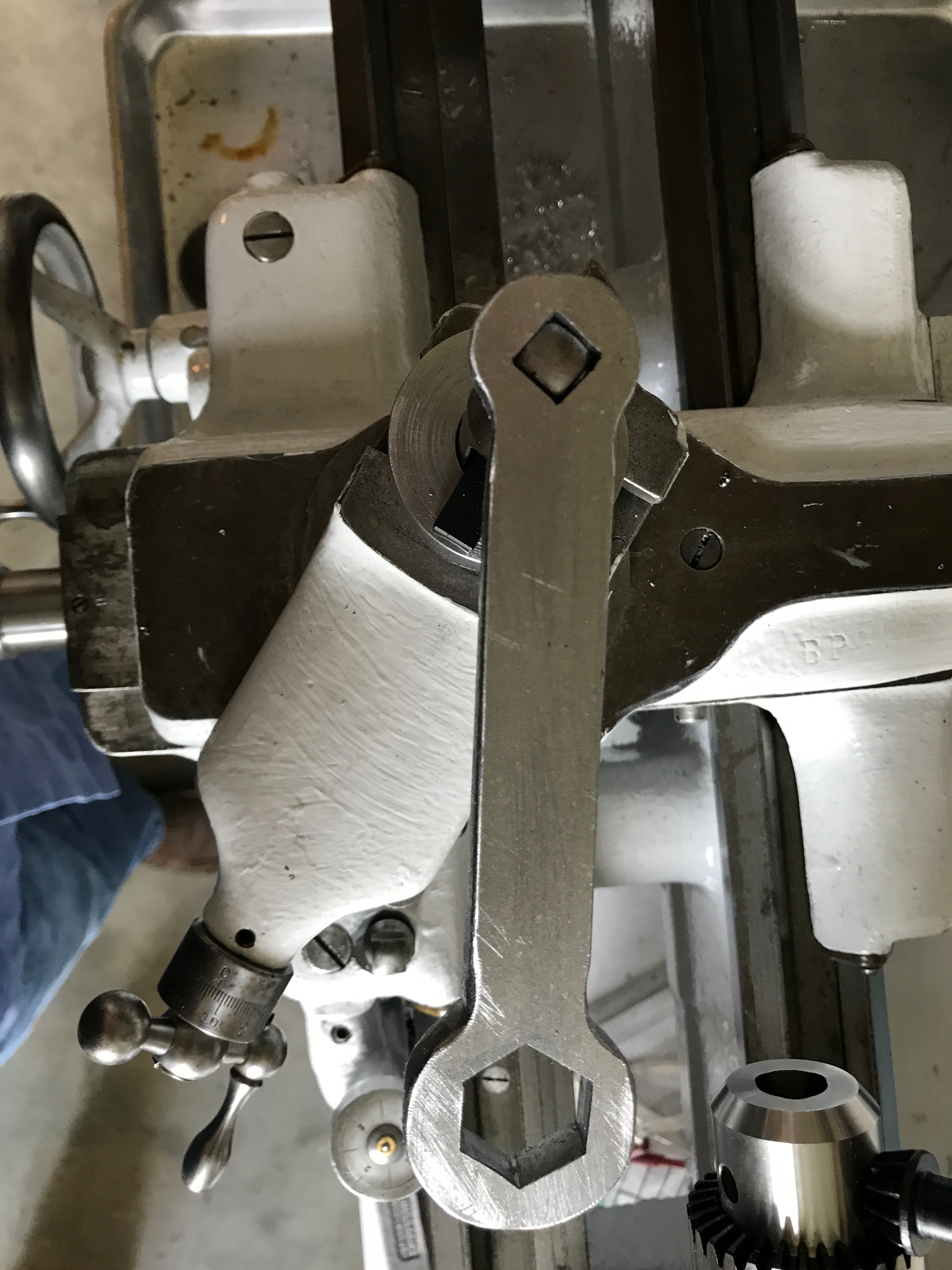
One final shot is of a wrench I made from 1/4" thick steel plate. Here it is shown on the square headed bolt in the cross slide toolpost. The hex end is used to tighten and loosen the tailstock. Both of these operations happen frequently. The wrench is routinely kept on the tailstock nut so it is always handy. (This nut can be seen in the picture above in the middle of the tailstock.) The square and hex holes were made by drilling round holes, which were circumscribed by the square or hexagon. The corners were then filed to scribed lines with a 3-corner file.
While working on some changes to tool location (8/29/19) I needed to move the belt covers. I decided to put the cover on the motor pulley belt. But before I did this I needed to finally deal with the belt slipping issue. The spindle was not correctly aligned with the motor pulley system, so the belt would slip off of the spindle pulleys to the left. I also noticed at this time that the lever tightening the belt needed adjustment for tightening different pulley combinations. Fixing this required two different adjustments. The two bolts holding the motor mount in place were loosened with a 7/32" hex wrench. Using a long straight-edge the two sets of pulleys were aligned left to right to fix most of the slippage. This was done by aligning the straight-edge against a spindle pulley and shifting the motor mount left or right as needed with a hammer and a board. The next task was making sure the pulley shaft was parallel with the spindle to minimize adjustments when flipping the belt tension lever. Aligning the straight-edge with the side of a pulley in the back showed how much the motor mount needed to spin around the right bolt. A little bit of pulling on one end and the pulleys were aligned. Rechecking the first alignment showed little movement so the two screws holding the motor mount in place were tightened. The belt no longer slips on any of the three pulley settings!
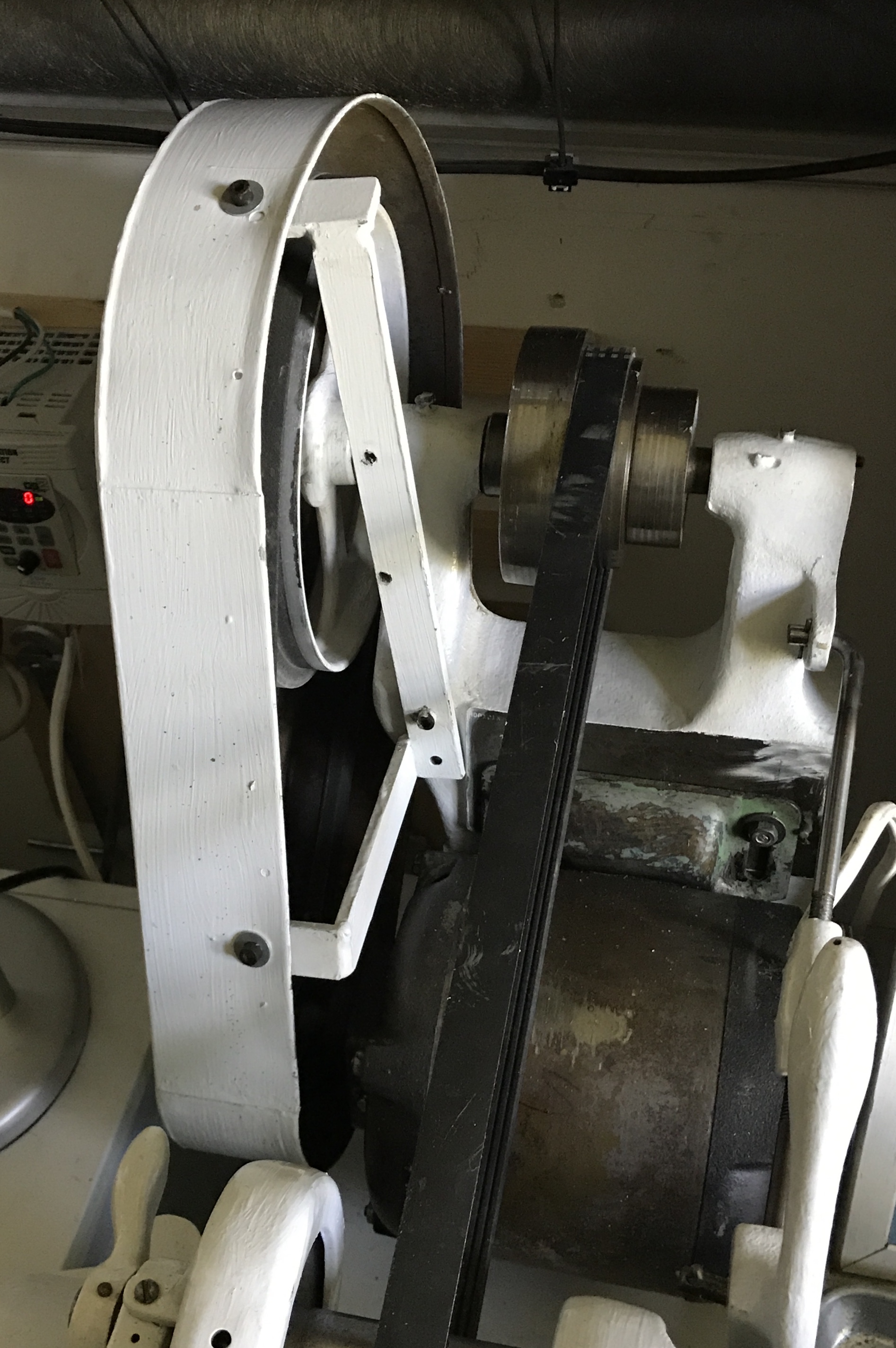
After some consideration I realized the bracket was designed to fit within the belt cover and bolt at its middle to the motor mount. I had some screws from the rebuild to attach the cover to the bracket with the help of some washers. The bracket's screw holes were a little corroded so some oil was put on the screws. The bracket was then bolted to the motor mount. Only one screw is used on the motor mount, but the attachment seemed sufficiently solid such that the cover did not rotate into the pulley.
An attempt was also made to install the other belt cover. A flange is built into this belt cover with two screw holes. They do not align with the two screw holes seen in the bracket photo above!! It is possible that only one screw is needed, but another issue arose. When put in place over the rear pulleys the cover does not fit properly over the spindle pulleys! It seems for this to fit the SB covers over the left and right sides of the spindle need to be removed. The entire setup seemed quite contrived. Since this is not an OSHA compliant shop I decided to forgo installing this belt cover.